Tuesday, August 3, 2010

update:

Over the past week we have been a little busy. Firstly we finished making the mouldings for the dolly, took the hull off the jig, laminated the inside, began fitting internal ribs.
We made the dolly last year after undertaking a basic TIG welding course at TAFE one night a week for a semester. As our final project we made the dolly for the cherub using 60x40x3 6061-T6 aluminium and used 25x1.5mm 316 stainless steel for the axles. All up in materials i think it cost about $200 plus $40 for wheels from eBay. So to fit it to the new boat all we needed to do was make a support for the hull. Note: The reason we used such heavy section aluminium was because of the way our boat sits on our 8x4 ft box trailer.

The above image is the centreboard case as it came out of the vacuum bag as you can see it pulled into the corners quite nicely and the overall finish is pretty good. The second image is the Styrofoam beginning to be melted out with acetone, after beginning this i realised it would have been a much better idea to leave to foam in there until it was in the hull as it is quite flimsy, so i stopped. Although i did notice that acetone was able to seep from the inside to the outside of the skin even though there was 4 layers of 200gsm glass, so it looks like i will need to paint the outside with a coat of resin to help make it water tight after it is in the boat.


I thought this image was worth adding this is the size of the extra reinforcing patch i used under the mast this was 1 200gsm carbon cloth on the 0/90 degree angle to the centre line (compared the the main hull skin at -+45)

I thought this was a good image to add showing the laminate wrapping around the hull/chine. Overall i was pretty happy with how the -+45 laminate laid over the hull and continued to stay approximately at -+45 as we worked towards the bow. I guess I'll see how good that decision was when we come to trying to fair the hull.


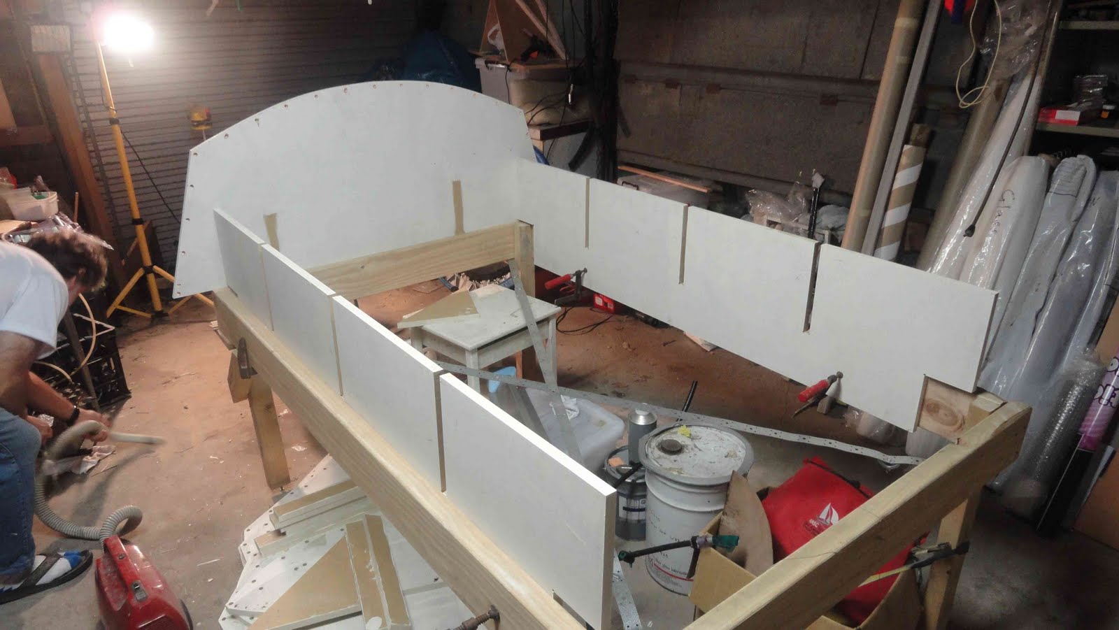
The first image is the jig again once once the hull was removed, the second showing how it was able to flat pack and store easily (to dismantle the jig only took 15mins and a electric screw driver)

This image is of the legs of the table/jig, i thought it was worth mentioning how we levelled the jig. Because our jig design had a table with 5 legs it was important to have the leg length adjustable to account for the un-even floor of the garage and our assembly etc. So we used a "coach- screw" in the bottom of each leg allowing the height to be adjusted simply with an open ended spanner.


This is the hull as it can off the jig.


This is the hull after we laminated the inside of the hull, same lay-up as the outside as it is very important to try and keep the laminated balanced so that when the hull is loaded up it doesn't try to warp. Also the floor ribs have been trimmed and ready to glue in and the centreboard case has been roughly fitted.


These are foils after we sanded the recess on the leading edges ready for their joining tape (1x 200gsm layer at -+ 45 to the centre line so it drapes well over the corner the fibres are at the right angle to resist the shear loads at the join)

Friday, July 30, 2010

Its go time....


Outside of hull was laminated last week, dolly and supporting cradle has been built and finished yesterday. The hull is ready to remove from the jig and flip over this Saturday. Then we will be able to laminate the inside on Sunday.


From there on in it is all hands on deck almost 6 weeks to the sailing season (looks like it might be a few weeks late). The two images above are some of the printed out templates of all the cockpit and interior. This is what I'm hoping will help drastically reduce our build time and where having a 3D CAD model of the boat should come into its own.

After the hull is laminated on the inside the internal structure will go into the boat in stages in the night time after uni during the next two weeks. Once the components are positioned and glued in place we will come back later and laminate / vacuum bag them in. I'll update with more photos after we flip the hull.

Tuesday, July 20, 2010

idea for laminating the centrecase


This is my idea for laminating the centrecase into the boat hull.

Firstly when we build the cradle, we make sure the area under the centrecase is well supported. Then mark out the area and grind away the foam so that we are left with the outside skin only in the centrecase area. Then the centrecase is trim, aligned and positioned. This is then bogged into place using a strong filler such as a glue powder or some sort of fibre filler and a small radius is made between the outside edge of the case and the hull skin.

Once this has cured and been neatened, the first laminate is done and cured. After this a foam wedge or filler piece is bogged into place using a light filler such as Q-cells and the second laminate is done over the top to tie everything in.

The reason for this double laminate process is because it allows you to distribute the load from the centreboard case into both the top and bottom skins and providing a large area to spread this load on the case its self.

Also note that in a loaded case such as a centreboard the hull exit is under twice the load of the centreboard head/floor exit so the hull exit needs to be particularly strong and the floor exit can be made a little lighter.

On the floor exit, I intend to glue a foam strip around the case to the height of the underside of the falsefloor so that it can just drop straight on top / around the case and be glued in place, then reinforce the opening from the topside of the floor.

Sunday, July 18, 2010

Above image is an assembly of the cad models i have been using to size and design components. The layout is not 100% of what i intend to use, but it has been extremely helpful in locating important points and dimensions. It has also allowed me to investigate the size and shape of the side tanks so that i can ensure it meets the class rules as well as provides enough space in the side tank to fit the spinnaker chute.


This is the centreboard case i intend to use, it allows the centreboard to have 200mm of movement fore and aft so that I can tune the centreboard position to the new rig and rig position. The adjustability comes from using different cover plates, both of the these plates on top and bottom are held together with a threaded rod. The cover plates are made custom for each centreboard position that is needed.


Above is an image of the cover plate in place, this top surface will be flush with the top skin on the false floor.


This is the centreboard case in the vacuum bag. It was constructed by shaping a piece of extruded polystyrene foam called "ISOBOARD", which is normally used for insulation. This was then laminated over with 4 layers of 200gsm glass cloth on the -+ 45 deg so that the cloth would pull into the tight corners. It was decided that 4 layers should ensure that the case is water tight.

Saturday, July 17, 2010

Hull laminated.... almost


Finally started laminating the outside of the hull today and halfway through ran out of carbon... looks like we used a lot more that we thought making the previous components for the boat. On the plus side, having the cloth on the -+ 45 degree allowed the cloth to draped over the chines quite easily. Also using scrapers/spatulas to wet out worked extremely well even on the curved surface of the hull. The peel ply was used to help soak up any excess resin and help prepare the laminate for secondary bonding of paint and fairing compound.

Looks like the next opportunity to pick up some cloth and finish the hull will be Thursday so hopefully not to much time will be lost. I will be able to pull the profiles for the cradle of the CAD model tomorrow so we can build the cradle while the hull cures. We will also be able to construct the centreboard case, member for the space frame, spinnaker chute and side tank mould in parallel to laminating the rest of the hull.

Wednesday, July 14, 2010

hull shell ready for laminating

Finally have finished putting foam onto the jig. We have faired in any rough areas and are ready to laminate the outside of the hull. The outside laminate will be 1x layer of 200gsm plain weave carbon cloth laid in a +- 45 degree axis with respect to the boats centre line. The main reason is to help increase the torsional stiffness of the hull and secondly the cloth will drape easier over the chines and sharp corners of the hull. A reinforcing layer will be placed over this to help spread take the load from the mast step and centre case area. This will be approximately diamond shaped and the fibre orientation will be 0/90 degrees to the hulls centre line. This laminate will be mirrored in the inside of the hull.

here are some photos of the hull ready for laminating:

Transom of the hull, about 10mm of curvature so almost flat.
Bow area certainly seems sharp and fine, although the intersection between the chine and bow is lower than the Matthew's hull. This means that the bow might not actually be as fine as i was hoping, I'll need to see two hulls together to find out how much finer we have made it.


A view from the back of the boat, its difficult to get a decent shot in the garage of the true shape of the boat so I'm looking forward to when we can take it off the jig and move it around a bit.

The current plan is to laminate the outside of the hull on the weekend then begin constructing the cradle next week.

We will be just using a simple wet-layup technique on the outside of the hull using plastic spatulas/scrapers as much as possible then applying a fine peel ply to help absorb excess resin and give a surface that's almost ready for secondary bonding.

Friday, July 2, 2010

Tiller looks fairly good, perhaps a little heavy at 370grams without clear coat paint, but it is very stiff due to the large cross section used at the box. So i should be pretty safe from breaking it if i try to support a bit of my weight on it.

Hopefully will be glueing the finaly pieces of foam on the hull tomorrow so we can get it ready to laminate during the week.

Wednesday, June 30, 2010

a few bits

Work has been slow over the past week or two with thesis work at uni ramping up a bit. Last night we laminated the new tiller for the rudder box, which is a fairly simple straight tapered tiller. I'll take it out of the vac bag tomorrow and let you know what the weight is.

We visited CST today and picked up a carbon recieving tube for the bowsprite 50mm ID x 400mm 2mm wall thickness long carbon tube (about 200g) and collected a qoute for a new mast. We are still unsure at this stage what we are doing about a rig, but considering we are planning to sell heart shaped box (3064) it looks like we will be buying a new one.

Our plan is to finsh the foam sheets on the hull this weekend and to laminte the outside of the hull by next weekend.

Monday, June 14, 2010

Its been a fairly busy weekend in the garage, with a significant amount of work completed. As can be seen above, we placed the sides onto the jig and they conformed pretty well. The sides were done in two pieces and joined slightly forward of the midpoint in a position that didn't experience much bending.


We also managed join the panels in the bottom of the hull and and glue them at the chine. Now only the forward sections of the hull need to be attached. Then we can begin trimming up the chines and getting it ready to laminate the outside of the hull.


We also managed to make a few components to help take to load off further down the track. The image above is a bracket for holding the self tacker track ends to the flat foredeck. This is the same arrangement as used on my old boat, but just made a little neater this time around. (The item above is cut into two brackets and trimmed up to be fitted to the boat)


This is the rudder gantry being laminated on the mould. The layers on the underside were laminated straight to the mould and then the foam plug was placed over the top and laminated over. The lay-up consisted of (1x carbon cloth, 2x 300gsm UNI carbon) each side and a 30 x 25mm foam core. The flat panel on the bottom is to prevent the gantry from "catching water" as this was a problem with my previous design (mainly because it was mounted to close to the water).

The above image is with the final later of carbon cloth ready for the peel ply, release film, breather and vacuum bag.


This is the gantry in the vacuum bag.

Above is the mandrel for our new boom. Simply a 20 x 20 mm steel box section with 75 x 50 mm strips of polystyrene foam glued each side. The steel is the keep the foam straight when shaping and laminating. My aim is to shape a boom with an elliptical cross section that tapers from goose-neck to boom tip. It will be maximum depth at the goose neck (class rule: must pass through a 104 mm ring) then taper to approx 60 mm at the tip end.

After this weekend the remaining components to manufacture are as follows:
  • Laminate tiller / build rudder stock
  • Laminate transom bar
  • Build side tank moulds / make side tanks
  • Design / build centre case
  • Foreword tension strut for rig space frame
  • Foot rests for floor
Then basically finishing the hull shell and putting it all together, easy right?

Sunday, May 30, 2010

Jig is finished


We managed to finish lining up the jig on Saturday and covered all the edges in packaging tape and plastic so that the foam will not stick to the jig. We put a tape measure of the jig and discovered that it had grown 20mm in length somewhere along the line. I spent several hours thinking about this today and for the life of me still can't find out where we went wrong. I was pouring over this drawings, 3D cad model and measuring everything on the jig, everything was as it was supposed to be except the final length. So once i work it out I'll let you know what it was. This does effect the boat (especially the bow) but it looks like we will be able to fudge / fair it in and we should be alright.

We began placing a full sheet (2200 x 1200 x 10 mm) of foam over the back half of the hull and tested out our methods of attaching the foam to the jig. We tried stitching the foam to the jig with a non-waxed sail makers thread and a small plastic spacer on top (so it would pull through the foam). We would then tighten this row of stitching in one go and pull the foam down to the jig surface.

At this stage its looking like the jig design of only using lateral supports, although simple to setup and line up it may not provide enough support to the foam sheets. As you can see from the last photo we are getting an uneven shape / surface at the chines. I feel this is because of several reasons, the first being that we are pulling to tight on the sewing thread and flattening the sheet against the top of the jig frame, rather than pulling it down to the one edge, which it is intended to sit on. To get around this we are going to try and develop a better way of attaching the foam sheet to the jig frames, which we and adjust each "stitch" on its own.

Secondly, because of the large sheet size it may require it to deform two much when it pulls down to the frame and forcing the foam to buckle or warp between the frame members. We can get around this by trimming the sheet into smaller pieces and joining them as we go, so that the joins form a "seam" such as in a sail.


The above image is of our rudder gantry that has been shaped and ready to be laminated

Monday, May 24, 2010

Intial jig setup

The photos below show the intial setting up of the jig, this was suprisingly quick and everything seemed to fit fairly well. The final accurate lining up of the jig will take place shortly. So from some of these photos you can begin to see the shape of the hull.

Also we had a quick look at bending the foam over the jig. It looks fairly good in places but we might have a bit of fun / difficulty in some areas. Also it will be interesting to see how the spacings go, as the foam was quite flexible / unsupported so only time will tell. If the foam is not supported enough, one option may be to laminate the inside of the foam strips with a light glass cloth to stiffern them up.


Fore-deck lay-up

This weekend was fairly successful in regards to boat building, with the last of the flat panels laminated and the hull jig initially setup.


Above is a table prepared to laminate a glass/carbon fibre plate so that it can be used to attach fittings to the hull. The plate is intended to be 5 mm thick and about 330 x 250 mm, this was approximately 24 layers of 200 gsm E-glass and 4 layers of 300 gsm UNI carbon.

The plate will be cut in to small strips that will be inlaid into the cockpit floor and side tanks so that threads can be tapped into them and fittings can be attached without the use of nuts and washers. I also intend to perform some testing on this method down the track to see how strong the threads are in the glass plate.
Above is an image of the glass plate under vacuum. Notice the black irrigation plastic and fittings used for vacuum bagging. By using these pipes I can make a manifold and have multiple vacuum lines coming off the same pump so that as the day progresses and I laminate more things i still have access to the vacuum without interrupting the previous layup. Also it allows a cheap way to put a valve/tap into the system, which means you can initially control the speed at which the vacuum is applied to the bag (which can be handy for tricky items, or tight bags).


Above is a lay-out I used on a sheet of foam to fit the bulkhead, floor support ribs and bowsprit 'V-beam' to try and get the best usage of foam. Some the panels are laminated, I will get the individual components printed full size on paper so that i can check the fit. Then I will be able to use the paper print out as a template to cut the panels. I'm hoping that this will allow me to speed up the bulkhead/floor rib fitting process considerably, which can take quite a bit of time to fit to the curvature of the hull correctly.


This is how we laminated all of our flat sheets. Firstly the panels were marked onto the foam sheet with pencil so we had an idea of where reinforcements and laminates would go. Secondly a slightly runny bog of epoxy and Q-cells (micro balloons) was made and spread over the entire sheet with a 150 mm wide plastic scrapper (this are very helpful for laminating flat panels and only cost about $1). This is to fill all the open cells in the foam with a lighter bog rather than with straight epoxy resin.


Next the uni-direction carbon reinforcements were laminated on the bulkheads and other areas. Then the 200 gsm E-glass was placed over the entire sheet, the epoxy resin spread out again using the 150mm plastic scrappers.

Peel ply is then spread over the entire laminate, then perforated release film to control the amount of resin removed during vacuum bagging. Finally the breather fabric was applied and the whole panel was flipped over and laminated on the other side.

Note: To make vacuum bagging easier, use a can of spray glue such as 3M super 77, to apply the release film to the peel ply and the breather to the release film. Otherwise it may move around and be difficult to put into the bag.


This is the flat sheet under vacuum in the bag, unfortunately we ran out of breather fabric so could only place it on one side.

This is the resulting panel after the release film and breather fabric was removed.

This is our rudder gantry, we started but laminating foam strips on the mould so that we could then shape it afterwards. This will allow is to laminate the gantry mould, place in the shaped foam core and laminate the other side in one go.