Sunday, May 30, 2010

Jig is finished


We managed to finish lining up the jig on Saturday and covered all the edges in packaging tape and plastic so that the foam will not stick to the jig. We put a tape measure of the jig and discovered that it had grown 20mm in length somewhere along the line. I spent several hours thinking about this today and for the life of me still can't find out where we went wrong. I was pouring over this drawings, 3D cad model and measuring everything on the jig, everything was as it was supposed to be except the final length. So once i work it out I'll let you know what it was. This does effect the boat (especially the bow) but it looks like we will be able to fudge / fair it in and we should be alright.

We began placing a full sheet (2200 x 1200 x 10 mm) of foam over the back half of the hull and tested out our methods of attaching the foam to the jig. We tried stitching the foam to the jig with a non-waxed sail makers thread and a small plastic spacer on top (so it would pull through the foam). We would then tighten this row of stitching in one go and pull the foam down to the jig surface.

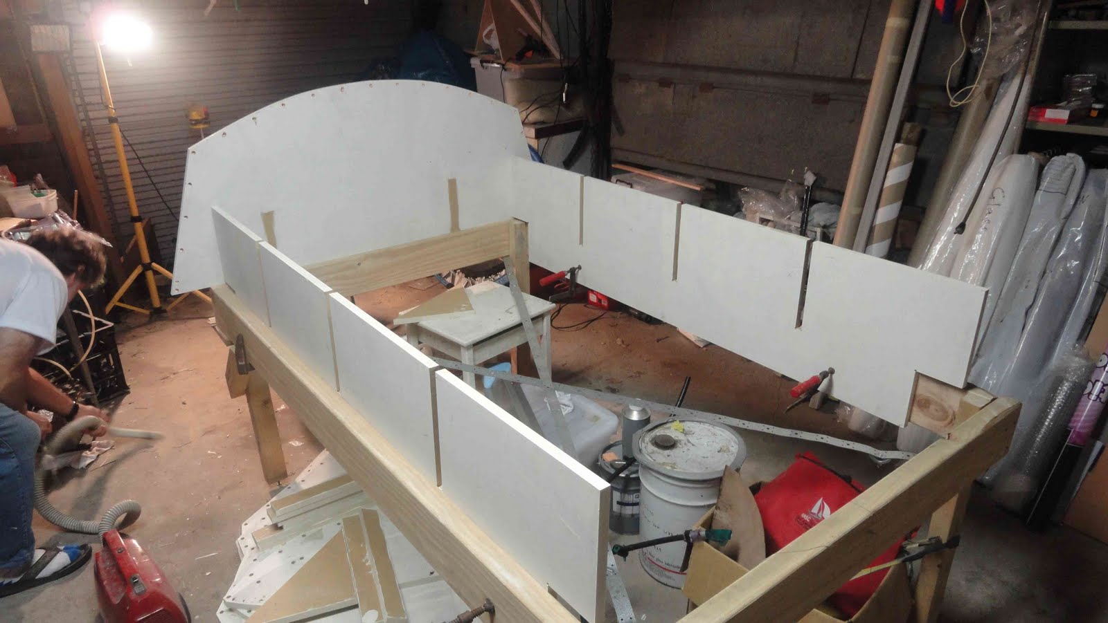
At this stage its looking like the jig design of only using lateral supports, although simple to setup and line up it may not provide enough support to the foam sheets. As you can see from the last photo we are getting an uneven shape / surface at the chines. I feel this is because of several reasons, the first being that we are pulling to tight on the sewing thread and flattening the sheet against the top of the jig frame, rather than pulling it down to the one edge, which it is intended to sit on. To get around this we are going to try and develop a better way of attaching the foam sheet to the jig frames, which we and adjust each "stitch" on its own.

Secondly, because of the large sheet size it may require it to deform two much when it pulls down to the frame and forcing the foam to buckle or warp between the frame members. We can get around this by trimming the sheet into smaller pieces and joining them as we go, so that the joins form a "seam" such as in a sail.


The above image is of our rudder gantry that has been shaped and ready to be laminated

Monday, May 24, 2010

Intial jig setup

The photos below show the intial setting up of the jig, this was suprisingly quick and everything seemed to fit fairly well. The final accurate lining up of the jig will take place shortly. So from some of these photos you can begin to see the shape of the hull.

Also we had a quick look at bending the foam over the jig. It looks fairly good in places but we might have a bit of fun / difficulty in some areas. Also it will be interesting to see how the spacings go, as the foam was quite flexible / unsupported so only time will tell. If the foam is not supported enough, one option may be to laminate the inside of the foam strips with a light glass cloth to stiffern them up.


Fore-deck lay-up

This weekend was fairly successful in regards to boat building, with the last of the flat panels laminated and the hull jig initially setup.


Above is a table prepared to laminate a glass/carbon fibre plate so that it can be used to attach fittings to the hull. The plate is intended to be 5 mm thick and about 330 x 250 mm, this was approximately 24 layers of 200 gsm E-glass and 4 layers of 300 gsm UNI carbon.

The plate will be cut in to small strips that will be inlaid into the cockpit floor and side tanks so that threads can be tapped into them and fittings can be attached without the use of nuts and washers. I also intend to perform some testing on this method down the track to see how strong the threads are in the glass plate.
Above is an image of the glass plate under vacuum. Notice the black irrigation plastic and fittings used for vacuum bagging. By using these pipes I can make a manifold and have multiple vacuum lines coming off the same pump so that as the day progresses and I laminate more things i still have access to the vacuum without interrupting the previous layup. Also it allows a cheap way to put a valve/tap into the system, which means you can initially control the speed at which the vacuum is applied to the bag (which can be handy for tricky items, or tight bags).


Above is a lay-out I used on a sheet of foam to fit the bulkhead, floor support ribs and bowsprit 'V-beam' to try and get the best usage of foam. Some the panels are laminated, I will get the individual components printed full size on paper so that i can check the fit. Then I will be able to use the paper print out as a template to cut the panels. I'm hoping that this will allow me to speed up the bulkhead/floor rib fitting process considerably, which can take quite a bit of time to fit to the curvature of the hull correctly.


This is how we laminated all of our flat sheets. Firstly the panels were marked onto the foam sheet with pencil so we had an idea of where reinforcements and laminates would go. Secondly a slightly runny bog of epoxy and Q-cells (micro balloons) was made and spread over the entire sheet with a 150 mm wide plastic scrapper (this are very helpful for laminating flat panels and only cost about $1). This is to fill all the open cells in the foam with a lighter bog rather than with straight epoxy resin.


Next the uni-direction carbon reinforcements were laminated on the bulkheads and other areas. Then the 200 gsm E-glass was placed over the entire sheet, the epoxy resin spread out again using the 150mm plastic scrappers.

Peel ply is then spread over the entire laminate, then perforated release film to control the amount of resin removed during vacuum bagging. Finally the breather fabric was applied and the whole panel was flipped over and laminated on the other side.

Note: To make vacuum bagging easier, use a can of spray glue such as 3M super 77, to apply the release film to the peel ply and the breather to the release film. Otherwise it may move around and be difficult to put into the bag.


This is the flat sheet under vacuum in the bag, unfortunately we ran out of breather fabric so could only place it on one side.

This is the resulting panel after the release film and breather fabric was removed.

This is our rudder gantry, we started but laminating foam strips on the mould so that we could then shape it afterwards. This will allow is to laminate the gantry mould, place in the shaped foam core and laminate the other side in one go.

Monday, May 17, 2010

false floor bagged


The above image is of the false floor (approx 1900 x 1320mm) being vacuum bagged while it cures. The lay-up for the floor was 10mm 80kg/m^3 foam with a layer of 200gm^2 E-glass layed on the +- 45 deg to the centreline and an extra layer of 130gm^2 E-glass at 0/90 on the topside. This lay-up was chosen for several reasons:

1. The cloth was layed on the +- 45 so that i can create a "torsion box" with the floor, hull sides and hull underside between the mast and the transom (all of which will have laminates on the +- 45). This it to help create a stiffer hull with reference to torsion induced between the skipper downwind (back corner of the boat) and the rig trying to rotate in the opposite direction.

2. The 130gsm layer was added to the topsurface because on my old boat 1 layer of 200gsm was not quite enough and pierced easily, while 2 layers of 200gsm was better it seemed slightly heavy.

Also note the floor has two lateral stiffeners, which are an additional thickness of 10mm foam and capped each side with 300gsm Uni carbon. This is to help increase the stiffness of the floor as there will only be two stringers running parrallel to the centreline that support the floor.


This is our new rudder gantry mould. This was made from 18mm MDF then brushed with epoxy. The design is based on the one off my old boat, but approx 50mm higher at the bottom gudgeon than the last design to help keep it clear of the water at low planing speeds.


This shows the foam strips being built up and glued into place. This will result in a member that is 30 x 20mm once it has been shaped and faired. Also notice this mould incorporates a flat section from the lower gudgeon to the hull, this is so a thin laminate (2x 200gsm carbon) can be layed there to help further prevent the gantry from dragging in the water.

Whats next?

by approx 29th of May i hope to have all flat panels laminated (fore-deck, floor ribs, bulkheads, bowsprite support, spinnaker tunnel and tension members to take rig loads). As well as the transom bar and rudder gantry laminated. Then we can clear off the work table and assemble the jig to start on the shell.

Sunday, May 9, 2010

Centreboard delamination

On Thursday morning last week we began releasing the centreboard from the mould. When we separated the two moulds halves we were very disappointed to see that one skin of the centreboard had torn its self from the foam core. Later it was found to be the electrical tape we had used to create a recess in the leading edge of the centreboard that had stuck heavily to the mould. This created a tensile force between the skin and core at the leading edge of board.


As can be seen from the image above the foam core failed in tension then the fracture propagated to the skin where the foam (not the foam / skin glue line) continued to fail in tension due to the peeling force. We then had to fill the void with straight epoxy resin and re-close the mould to rejoin the skin to the foam core.

This is what we learnt from it:

1. We should have put PVA or wax on the electrical tape and not just relied on the smooth plastic surface for a clean release.

2. That the foaming resin is a lot weaker than we first thought after two days of cure time. The data sheet recommends that the foam be post cured at 50 degrees for 16hrs to obtain the best properties.

Note: The board in the unpainted state weighs 3kg

Tuesday, May 4, 2010

Centreboard

This morning we joined the centreboard together with the expanding epoxy foam. We poured in 1.8kg of expanding foam it looks like about 100g of foam has expelled out of our outlet hole in the mould. The below images are of the centreboard mould clamped together and also of a footstop mould made today.

The footstop will basically be a carbon fibre (clear finished) foot rest for the crew to use when getting out onto the trapeze. There will be one each side of the centreboard case approx 600mm long and positioned parallel to the centre line of the boat. The mould was made by folding 3mm sheet aluminium into the given shape.


Monday, May 3, 2010

Questions

Also if anyone has any questions at anytime please feel free to ask by commenting below the post and i'll do my best to answer them as soon as i can.

Cheers Adam

Releasing rudder


The rudder released from the mould relatively easily, except the electrical tape we used on the leading edge to create a hollow for a carbon tape later on turned out to hold the blade in the mould and took a little bit of work to release. The blade at this stage has an extremely fine trailing edge, which we will trim back a little to help prevent damage. Although when releasing the blade it did look like there my possibly be an air pocket or a section on the leading edge that hasn't bonded properly. So i will need to do some investigating into that later in the week. Also rudder blade out of the mould was 1.5 kg I think the amount of carbon that went in was 500g on the rudder (total) and 900-1000g in the centreboard (total)? i probably should have written that down, mybad.

Although there is also clear 2-pack paint to go over the carbon finish to;

1. Help fill any hollows and give a little bit of material to fair the board with.
2. To make the carbon look good.

Tip: When trying to release something such as a rudder blade from a mould, try to work from the head of the board as this is the stiffest end (as opposed to the tapered tip). So that instead of flexing the board in mould, you are actually lifting it from the surface effectively.